Miscelaneous topics explained #
Solver / Numeric Integration #
Solver substeps #
Solver Substeps are subdivisions of the Unity physics time steps that are used for calculating the internal torques, forces and momentums at every block in the vehicle. The solver in VPP can use from 1 to any number of substeps. This setting can be configured per-vehicle.
The more substeps, the more precise are the results but CPU usage is increased. However I've noticed no significant penalty on using 1 to 8 substeps. CPU usage as shown at the profiler gets increased from 10 substeps and above.
Tip
As rule of thumb the minimum recommended substeps for a vehicle is . Thus, 8-wheeled vehicles with all-wheels-drive shouldn't use less than 4 substeps. AWD cars should use 2 or more substeps.
Some subjective recommendations:
| Substeps | Comments |
|---|---|
| 1 | Non-player vehicles that don't require precise physics such traffic, parked cars, etc. |
| 2 | Minimum recommended for any player vehicle or "active" non-player vehicle (i.e. opponents) that require precise physic behavior. |
| 4 | Good value for having reasonably precise results. |
| 8 | Recommended value for having good precise results. Profiler tests show no significant penalty on using from 1 to 8 substeps. |
| 20 | Maximum recommended value. At Unity's default physic step (0.02s, 50Hz) the vehicle does its internal calculations at 1000 Hz (20 x 50hz). |
More than 20 substeps is typically not necessary nor recommended. Some blocks may exhibit numerical oscillations on high amount of substeps.
Final value depends on the specific project: CPU requirements, number and type of vehicles, expected precision...
Should I change the Unity's physics timestep? #
There's no need for changing Unity's default physics/fixed timestep (0.02, 50Hhz). Within Vehicle Physics Pro you can configure the number of solver substeps in a per-vehicle basis.
Some calculations and data are extracted out of the Unity physics engine: velocity and downforce. These are calculated at the Unity's physics rate. Tire forces are also applied at this rate.
If you really need to get the most precision out of the vehicle physics then you can modify the Unity's fixed timestep to 0.01 (100Hz) or 0.005 (200Hz). This is NOT recommended because it can dramatically increase the CPU usage footprint because of the physics. Also ensure the solver substeps are adjusted accordingly: if fixed timestep is 0.01 (100Hz) and your vehicle is set to 10 substeps, then the calculations for that vehicle are done at 1000Hz.
How to measure the precision of the integration? #
Ensure you understand the difference among accuracy (or trueness) and precision. Vehicle Physics Pro is fully accurate in its design, implementation and behavior giving reasonably precise results. Precision affects the the specific numeric values only, and depends on solver substeps.
A simple way to measure the precision is setting the Differential Type to Locked in a RWD (rear wheel drive) vehicle. This enforces both drive wheels to rotate at the same rate. Then drive around gently and do some left-right turning while watching the rotation rate of the drive wheels at the telemetry.
When using 1-4 substeps the wheels are "pursuing" each other when changing the steering direction, but won't likely spin at a the same rate unless steering is kept steady. The more substeps, the faster they will catch each other's rotation rate. With 10-20 substeps the difference in their rates will always be within 1-2 rpms only.
Vehicle shakes or becomes unstable #
If the vehicle becomes unstable at high speeds then either increase the tire side deflection rate or disable the tire side deflection feature. Low side deflection rates at high speeds can enter in resonance with lateral forces destabilizing the vehicle.
Pro-Tip
Tire side deflection rate can be used to simulate tires targeted to different speeds. Tires with low rates become difficult to drive at high speeds.
If you observe values that are quickly oscillating at the telemetry in a way that visibly affects the vehicle (shakes) then adjust the solver substeps:
- A single substep is likely to cause oscillating values, but usually they don't have a noticeable effect.
- 2-8 substeps are pretty stable in most situations.
- More than 20 substeps are not recommended as the numerical oscillations can get magnified.
Advanced integration parameters #
Damping #
Numerical damping heps preventing resonances. When integrating the vehicle dynamics, the reaction torque is accounted from the previous integration step. If this value is used as-is, it might happen the integrated sequence to be quickly oscillating between two values.
The damping ratio (exposed as damping in the affected blocks) counteracts this effect by
multiplying the reaction torque before entering the equations. This helps the solver to reach a
stable result without numeric oscillations or resonances. The drawback is that the actual numeric
result might be less precise.
Typical values are 0.9 - 1.0, with 1.0 meaning no damping is applied. In most cases the best value is the block's default and it shouldn't need to be modified.
Blocks that expose damping are those that use the reaction torque in their calculations.
This includes Engine, Gearbox (for the Park mode) and Differential, among others.
Viscous coupling rate #
The viscous couplings (a.k.a. "lock ratio") should be always integrated at a given rate. Otherwise,
the computed torque would depend of the current integration rate and solver substeps. Defining a
fixed rate (VehiclePhysics.Solver.viscousCouplingRate) ensures viscous couplings to result in the
same torque values for a given lock ratio, independently of the actual integration rate or substeps.
Important:
Modifying the viscous coupling rate results in different physics behaviors! Blocks that implement a viscous coupling will modify their torque / angular velocity results for the same situations.
Blocks affected by VehiclePhysics.Solver.viscousCouplingRate include:
- Engine: clutch in LockRatio or TorqueConverter modes
- Differential: lock ratio in Viscous mode
- TorqueSplitter: stiffness parameter
The configured rate must be equal or greater than the physics solver rate (physics delta time and substeps). Otherwise the viscous couplings will be integrated at the actual solver rate.
In most cases you shouldn't need to modify the solver's default values.
Engine #
It's difficult to stall #
Increasing the Stall Sensitivity setting makes the engine more sensitive to rpms below idle. Check out the calculated stall rpm value at the inspector, below the engine graph.
The Idle Control setting defines how the idle rpms are enforced:
- Active: Vehicle's electronic system actively applies as much torque as available for keeping the idle rpms.
- Passive: Engine just applies a constant torque that compensates the friction at idle rpms. Works better with a steep friction curve at idle rpm. Also, requires the throttle to be applied for starting the engine with the ignition key.
The Passive mode is much easier to stall, but requires configuring the engine friction in a specific way.
Stalls too easy #
Disabling Can Stall ensures the engine never stalls.
Assuming Can Stall is enabled, you can:
- Reduce the Stall Sensitivity value. Check out the calculated stall rpm value at the inspector, below the engine graph.
- Set Idle Control to Active.
- Change the Clutch Type to Torque Converter in Clutch Settings. This clutch type doesn't require to be actively engaged. Vehicle may stall at rare situations, like going backwards after spin.
Pro-Tip
Having a Torque Converter with a manual transmission is not a common setup but can greatly improve the gameplay. The user doesn't have to worry about clutch and still can apply throttle gently in low speed maneuvers.
How to ignite the engine at the beginning of the scene? #
Two methods:
-
Disable Can Stall. Engine will be always on, without possibility of stall.
-
Keep sending the value "1" to
InputData.Key(Input channel) via the Data Bus until the valueVehicleData.EngineStalled(Vehicle channel) returns "0". Then send a "0" toInputData.Key.This procedure actually moves the ignition key to the Start position. Once started (vehicle is no longer stalled) the key is moved back to the Acc-On position.
How to configure the horsepower (HP)? #
In the engine you can configure torque only, not HP. Torque is the actual value the engine transmits to the blocks downstream. Engine power or HP is just the torque multiplied by the angular velocity. In the engine setup you specify directly:
- How much torque you want at the flywheel at two given rpm values, named idle and peak.
- How the engine friction behaves with angular velocity.
- The rpm limit the engine is designed to operate at. The torque mechanically becomes zero at that point.
The block calculates the engine values out of these settings. The torque curve (green curve in the graph) is calculated by combining friction with the specified torque values and rpm limit.
The torques at the specified rpms can be extracted directly out of actual engine torque curves. All you have to do is to adjust the friction curve until the actual torque curve and resulting HP match the real data.
Rpms decrease very slowly when releasing the throttle #
The rate the rpms decrease when releasing the throttle depends on the engine friction and the engine inertia.
- The Engine Friction is shown as a red line in the engine inspector. The more friciton at a given rpms, more brake effect the engine will produce when no throttle is applied.
- The Engine Inertia setting also affects the rpm change rate overall. It's the rotational equivalent for the mass. The more inertia, rpms will change slower. The less inertia, rpms will change faster.
Too much engine friction makes the wheels rotate backwards #
This might be either a correct behavior, or an indication that more solver substeps are required.
Real driving tip
Releasing the throttle in a car driving forwards makes the engine friction to brake the vehicle. Too much engine friction can force the wheels actually spin at less speed than the road underneath, causing wheel lock. In racing cars this effect is typically observed when shifting down, and is compensated using the heel-toe technique.
A single wheel rotating backwards due to huge engine friction is likely caused by the differential. This is a correct behavior. It's most likely to happen in open or low-preloaded differentials, and specially when approaching a corner. The outer wheel getting most of the weight combined with the huge engine brake could make the inner wheel to spin backwards. Can be easily seen with a LEGO differential ;)
You can verify whether the behavior is correct or not by setting the differential type to Locked. If now the wheels spin forwards when engine friction is applied, then the behavior with the other differential type is correct.
If the effect can be observed even with a locked differential then try increasing the solver substeps (up to 20, assuming a default Unity physics timestep of 0.02). Wheels should rotate forwards but at less speed than the road when releasing the throttle. As extreme fix, you could try setting the Unity physics time step to 0.01 and 10 solver substeps in the Vehicle Physics solver. Note that this will increase the overall impact of physics in the CPU usage.
Understanding engine curves #
Moved to the Engine Block section.
Vehicle setup #
Understeer, oversteer, high speed vs. low speed #
Tweaking vehicles in VPP is much like tweaking real vehicles. Same rules apply.
- Inertia
- The inertia represents the distribution of mass within the vehicle and defines its natural behavior. It plays a critical role in the handling and the understeer/oversteer effects. For example, vehicles with the engine in the rear part will behave in a different way than vehicles with the engine in the front, even with all other properties (mass, center of mass) being the same. VPP provides a component (VPPChassisInertia) for configuring the inertia properly.
- Low speed
-
The behavior at low speed may be configured with the suspension (springs, dampers, anti-roll bars) and weight distribution (center of mass).
- High speed
-
Behavior at high speed may be adjusted with aerodynamics.
- Configure a couple of VPAeroSurface components in your vehicle. One should be positioned at the front axle, and the other at rear axle.
- Configure Downforce Coefficient at both components. This will define how much weight (= downforce) will be added to each axle as the speed increases. If the front axle receives more aerodynamic downforce than the rear axle, then the vehicle will get oversteered at high speeds. If the opposite applies, the vehicle will get understeered at hight speeds.
You can use the Performance Analysis component in the Wheel Load mode so you could see the effects of the aerodynamic components graphically:
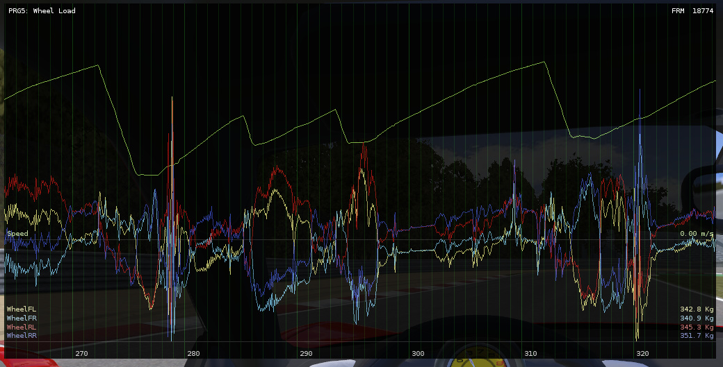
The above is an example of the F458. You can see how as the speed increases (upper line) the wheel load also gets increased for all wheels. If you analyze the chart carefully, you'll realize that the rear axle receives more downforce with speed that the front axle. The downforce coefficients in this case are 0.4 front and 0.8 rear.
- Braking
-
Behavior on braking at any speed can be easily adjusted with the brake balance.
A correctly configured brake balance typically routes more braking power to the front wheels than to the rear wheels. This accounts for the weight shifting while braking. Moving the balance further to the front results in more understeer behavior, while moving it to the rear results in more oversteer.
Too much understeer! #
- Configure the vehicle inertia
-
The inertia represents the distribution of mass within the vehicle and defines its natural behavior. An understeering vehicle may be turned into oversteering by moving the distribution of mass to the front part. Use VPPChassisInertia for configuring the inertia of the vehicle.
- Automatic steering angle limit
-
This setting in VPVehicleController limits the maximum steering angle to the value that provides the most lateral grip at the actual vehicle speed. This ensures the wheels are performing to their maximum grip, thus allowing to experience and configure the vehicle's handling properly.
- Aerodynamics
-
Aerodynamic components provide extra downforce with the speed. This downforce increases the grip at the tires. Balancing the amount of aerodynamic downforce among front and rear axles can configure the understeer / oversteer behavior at high speeds.
Aerodynamics requires keeping an eye on the suspension (you can use the Telemetry). The extra downforce will compress the suspension as well. The suspension must not reach the 100% compression (1.0) or unwanted effects will occur. Stiffer springs or progressive suspensions might be required for avoiding that.
- Force feedback
-
Allows the use of steering wheel controllers for feeling the actual grip of the tire while cornering.
Still, note that most real vehicles tend to understeer as natural behavior.
I'd like to quote this forum post from Stefano Cassillo, developer of the Assetto Corsa simulator, regarding lateral friction:
Tire lateral grip
It depends a lot.. a typical road tire will give you 1.0 - 1.1 G.. with load sensitivity and all you should get close to 1.0G on a skidpad. A normal road car with 1.0G lateral acc is considered VERY good (ie. the BMW Mini scores a tad less than 1.0G and is considered a very good handling car).
Casual players usually find this VERY low.. this has lots of possible explanations:
No real experience with real cars.. and I mean track experience in a competitive way, not the kind of experience you get being an idiot on public roads.
The result of 1 is that no driving skills are developed... typical sign, Joe-I-Go-Fast goes too fast into a corner, the car will understeer and he turns more into the corner, making understeer worse and going even more wide into the wall.
They are used to other games either arcade a-la PGR or F1 games where cars have huge amount of grip.
Driving Aids explained #
A proper setup of the driving aids based on the vehicle and the control methods makes the vehicle as much easy / difficult to control as desired. They are almost mandatory when the vehicle is controlled with keyboard or touch input. In analog setups (steering wheel devices) the driving aids overcome the limitations of the simulator giving the feedback the driver gets in real vehicles. At the same time, the simulation remains physically realistic.
Traction control #
Limits the engine throttle so the drive wheels produce a limited amount of slip. Traction Control has three working modes:
- The Street mode prevents any slipping, keeping the tire at the adherent state.
- The Sport mode aims to keep the tires at their peak slip (maximum traction).
- In the Custom Slip mode you can configure exactly the amount of slip the drive wheels are allowed to slide at.
The Ratio setting allows fine-tunning the traction control from 0 (disabled) to 1 (fully engaged).
Steering Aids #
- Steering Limit
-
Automatically reduces the available steering range based on the speed of the vehicle. This enforces a steering angle according to the current speed. Read Understanding steering, friction, and lateral slip / forces for understanding the effect of this aid.
Steering Limit has three working modes:
- The Street mode leaves a very narrow steering angle that prevents the front wheels to slide laterally (tire's adherent slip). This forces the driver to reduce the speed hugely in order to do sharp turns.
- The Sport mode leaves the steering angle that produces the most sideways grip. This is perfect for racing as the tires are pushed to their maximum performance.
- The Custom Slip mode allows configuring the amount of slip the tires are allowed to slide at on steering.
Pro-Tip
The Street and Sport modes calculate the angle based on the ideal friction value (i.e. Ackerman and TOE are not accounted for). Achieving the maximum lateral acceleration involves performing skidpad-like tests on the vehicle for finding the best slip value for the Custom Slip mode.
Vehicle's lateral sliding is accounted for correctly: when this happens the limit is relaxed in the counter-steer direction, so the vehicle can be recovered from losing the rear end even at high speeds regardless of this setting.
The Proportionality setting defines whether the steer input is just clamped against the limit angles (0), or it's used as proportional ratio within the available range (1). This value has no effect if the Steering Help is also enabled and Priority is Help First.
- Steering Help
-
Automatically moves the steering wheel to the direction that keeps the vehicle controlled under lateral sliding. The user's steer input is applied as offset to this assisted steering angle.
-
Keyboard, touch controls: use a large Help Ratio of around 0.8 - 0.9. All the user has to do is tapping left-right for applying minor corrections for controlling the vehicle's direction. Using a Help Ratio of 1 makes really hard to loose the control of the vehicle.
-
Steering wheel and analog devices: reduce the Help Ratio to 0.4 - 0.6. This way the user has most of the control, while the Steering Help provides a further hint.
-
- Priority
-
When both Steering Limit and Steering Help are enabled this setting defines how they should work together to provide a specific behavior:
- Prefer Drifting: The vehicle tends to conserve the sideways sliding velocity, with the user input being applied as corrections to the direction.
- Prefer Go Straight: The vehicle tends to keep the straight direction. It steers and/or drifts when the user applies enough steering in a given direction, otherwise the vehicle returns to straight driving.
Pro-Tip
Steering Limit + Steering Help + Limit Proportionality can be configured so the vehicle converges itself to stable drifting without applying any steering input, just throttle:
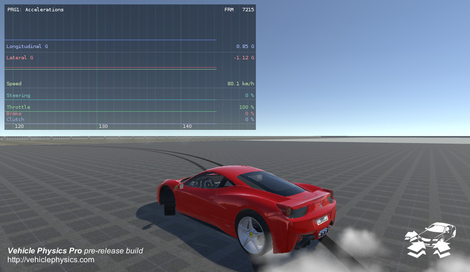
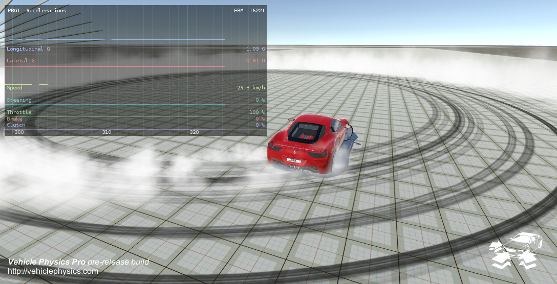
In this example, the driving aids with Limit Proportionality = 0.6 allows the vehicle to converge to a perfect drifting circle (left picture). Increasing the proportionality reduces the drifting radius (right picture, proportionality = 1). This feature requires the steering range to be wide enough for the system to compensate the lateral sliding properly.
F1-style suspension setup #
This experiment is based on the Ferrari F458 prefab. Open any scene with the F458 and modify these settings:
- Rigidbody: Mass = 580
- Vehicle Controller: Tire Impulse Ratio = 0.3
- Aero pack > Front > Downforce Coefficient = 1.1
- Aero pack > Rear > Downforce Coefficient = 1.3
- WheelColliders > [all wheels] > Suspension Distance = 0.08
- WheelColliders > [all wheels] > Spring Rate = 122000
- WheelColliders > [all wheels] > Spring Damper = 2000
Now the F458 weights the same as a Formula-1 car, has a F1-style suspension and a highly efficient aerodynamic pack.
As the speed increases the suspension gets compressed by the downforce and the vehicle can perform sharper turns. In this extreme case it can reach even 6 - 7G. The springs get compressed until supporting up to 5x the original weight of the vehicle.
The springs should either have room enough or be strong enough for supporting all the extra downforce at high speeds. The Performance Analysis component in Suspension Travel mode is perfect for checking this out. Here you can see how the suspension height decreases (suspension gets compressed) as the speed increases. When the suspension charts cross the bottom line the suspension has reached its limit:
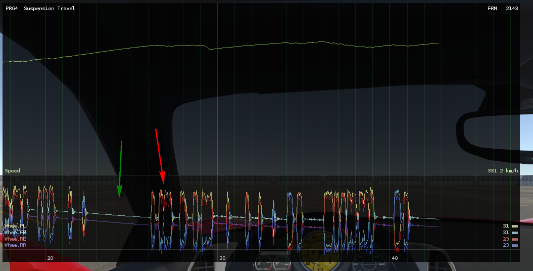
There's enough suspension travel available when the vehicle is driving straight (green arrow), but the outer wheels easily hit the suspension limits at sharp turns (red arrow). This effect can also be mitigated with stiffer anti-roll bars.
Extreme suspension setups might cause "jittery" behavior at some situations. There are two critical factors about this:
- Suspension damper (VPWheelCollider)
- If dampers values are too large for the current vehicle mass, then the vehicle will exhibit jittery behavior. As rule of thumb, a correct base value for the damper is rigidbody.mass*2. Smaller values result in bouncy suspensions, while larger values (be careful) result in damped suspensions.
- Tire Impulse Ratio (VPVehicleController)
-
This is the impulse force that keeps the tires adherent to the surface when they're not sliding. Under some circumstances this impulse might be too large so it "overshoots" the adherent state. A new impulse is then applied in the opposite direction, causing a noticeable shaking. This may happen, for example, as result of the extra downforce caused by aerodynamics. These cases can be identified easily as the lateral tire forces quickly oscillating among large positive and negative values:
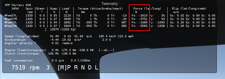
Reducing the tire impulse ratio solves this problem. It should be as large as possible without causing issues. If Tire Impulse Ratio is too small the tires would feel "sluggish" when reaching the adherent state.
Drift settings #
Drifting in practice #
Load the Gymkhana scene (search for Gymkhana at the Project). This is the scene used for recording this video.
The vehicle is configured to be controlled by the keyboard. The main settings adjusted for the drifting behavior are:
- Transmission
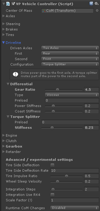
- All-wheel-drive with Torque Splitter. The drive power goes to the rear axle. If the rear wheels slip, then part of the drive is routed to the front axle.
- Differential gear ratio
- A higher ratio reduces the top speed and transmit more torque to the wheels. This allows configuring a good drifting power in the 2nd gear.
- Torque splitter
- Configures the ratio of drive power that gets routed to the front axle when rear wheels slip. This allows configuring the handling while drifting. If ratio is too small the vehicle will mostly do poorly controlled donuts. If ratio is too large the vehicle won't drift. A correct balance results in the proper behavior.
You might also configure the differential type and lock ratio. Typically, a locked differential is known to be the best setup for drifting. However, in this particular case this would affect both front and rear differentials. Having a locked differential at the front axle causes a very bad handling. I've tested a regular viscous differential to do a good job overall.
Drifting in theory #
Use the same settings as real drift cars. Hints:
- Center of Mass and weight balance
- The longitudinal position of the center of mass should distribute the weight around 52/48 (52% on the front and 48% on the back).
- Differential
- Choose either Locked or Clutch Pack with increased pack friction and/or decreased power angle. The goal is the differential to get locked when applying power easily.
- Engine and gearbox
- Engine should be powerful enough to make the rear wheels to slip rather easily. The gear ratio and the throttle should be tunned for keeping the wheel's spin rate under control. Too few spin rate and the car won't drift. Too much spin rate and the vehicle will drift too much and loose control. A rev limiter can be set up in the engine for ensuring that the rear wheels don't exceed the optimum spin rate.
- Driveline
-
A configuration that works good is all-wheel-drive with a center Torque Splitter. The drivetrain is configured to power the rear axle, but part of the drive power is routed to the front axle. The amount of drive that gets routed is defined by the parameter stiffness of the Torque Splitter:
- 0 = disengaged. No connection between front and rear axles.
- 1 = locked. Both axles are connected with a rigid axle (same as Locked differential).
Any value in between (default is 0.25) configures the behavior of the vehicle when rear wheels are skidding. A good value gives the driver a nice control on the drifting direction.
This is quoted from WhateverMan at gamedev.net:
ALSO about drift cars, what I said earlier, 52/48 was 52% on the front and 48% on the back. Drift cars are Front Rear Layout cars. You need more weight on the front because you control with your wheels and lighter rear to get more wheel spin. Later you use rear wings aerodynamics to balance the angles with speed requirement.
Handbrake has little effect in AWD #
The best solution is to use a driveline configuration with a center Torque Splitter and disengaging it when the handbrake is applied. This disconnects the rear axle from the front axle (and the rest of the driveline), so rear wheels can get freely locked without affecting the front axle.
The option for disengaging the central driveline element when handbrake is applied can be found at the component VPStandardInput.
In addition you can use the splitter's preload settings for configure how much torque is allowed to be transmitted while handbraking. This allows a great control on how much the vehicle gets affected by the handbrake.
The reason for this behavior of the handbrake is that in AWD both axles are connected via center differential or torque splitter. Thus, locking the rear axle will affect the front axle as well. Most likely the front wheels will be braked as well.
If the center differential is configured as Open then the front axle is almost unaffected by handbrake. However, an open center differential is not good for donut/drifting because the power will be mostly routed towards the front wheels (as they're typically less loaded when applying throttle). On the other hand, setting up the center differential as Locked means that the handbrake will effectively affect both axles equally, thus acting like a regular brake. A Torque Splitter with stiffness and/or preload > 0 will also transmit part of the effect of the handbrake to the front axle.
Car bouncing or shaking over the ground #
This kind of problem most probably related with the damper value. Surely the damper values are too large. Try either reducing them, or learn how to configure the damper properly as described below.
Watch your damper!
The suspension damper is implemented very very badly in PhysX 3 (the underlying physics engine in Unity 5). Configuring a correct value is critical for the vehicle stability.
Configuring the damper value
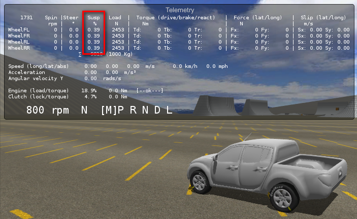
First, check out the suspension compression ratio for your wheels in runtime. This ratio is
reported by the Telemetry, or via scripting with VPWheelCollider.compressionRatio:
If you encounter issues at high speed, then put your vehicle at those speeds and check out the actual compression values. Aerodynamic forces might be compressing the suspension further at high speeds.
Then open the VPWheelCollider inspector at the editor by selecting any wheel component in your vehicle:
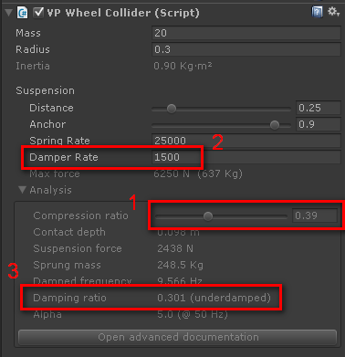
-
Specify the compression ratio you want to study under the "Analysis" section. This section doesn't have any effect on the actual configuration. It just makes the calculations and shows the results.
-
Configure the damper rate value at the suspension settings.
-
Watch the resulting damping ratio value for that damper value.
This damping ratio defines the behavior of the vehicle according to the dampers. I've studied several settings with these results:
- < 0.3: safe values working as expected.
- 0.3 - 1.0: mostly stable but may expose unrealistic behaviors such as the vehicle being "glued" or artificially pushed towards the ground.
- 1.0 - 1.6: potentially unstable and unrealistically behaving on many situations.
- > 1.6: mostly unstable, bounces, shakes, etc.
I'd recommend you to use damper values so the damper ratio doesn't go beyond 0.3 - 0.4 at most for hard suspensions. Values around 0.1 - 0.2 provide nice under-damped (slightly bouncy) suspension effect.
Learn more: How Suspension Works
Custom components and vehicles #
How to control the vehicle my way? (mobile controller, AI, ...) #
Create your own input component, i.e. CustomInput, for sending your input values (throttle, brakes
steering...) to the vehicle via Data Bus. Use the included standard input
component VPStandardInput.cs as example on how to send the values. Add your custom input component
to the vehicle GameObject instead of VPStandardInput.
Do not modify the original scripts, as future updates may override your changes. The package is designed so any functionality could be added via custom scripts.
Scaling vehicles #
Use of scale has these conditions:
- Scale must be 1 in the vehicle's root GameObject, which holds the Rigidbody and the VPVehicleController components.
- Scale must be 1 in all VPWhelColliders components and along their ancestor lines up to vehicle's root.
You can scale the GameObjects containing visual meshes only. A good practice is to put all the visual components under a child GameObject in the vehicle's root. This way scaling this child object would scale all visual meshes as well.
You'll have however to manually relocate the GameObjects containing the VPWheelCollider components to their scaled positions, then modify radius, suspensionDistance and center accordingly. Do not modify the transform.scale value of a VPWheelCollider component or any of its ancestors.
How many wheels are grounded? #
Check out the property wheelState in any controller that inherits from VehiclePhysics.VehicleBase.
It lets you access the array of state variables for all wheels. You can use foreach () and count how
many wheels have the flag wheelState.grounded enabled.
VPVehicleController (derived from VehiclePhysics.VehicleBase)
adds the wheels to the wheelState array in the same order as they're specified in the Axles
property. Typically, the order is front to rear, left and right. But this order not strictly
enforced, it might vary if the user specifies axes in a different order. Also, custom vehicle
controllers might add the wheels to the array in a different order. The recommend order is
Left1, Right1, Left2, Right2, Left3, Right3, etc. being 1, 2, 3, ... the axles from front to rear.