Tires #
The Tires section defines the tire friction curve for the wheels in the vehicle.
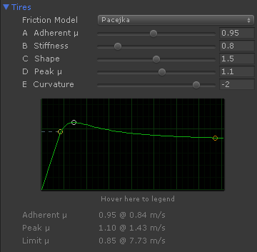
- Horizontal axis
- Slip velocity in m/s (each vertical green line is 1 m/s), that is, the wheel speed difference at the contact patch.
- Vertical axis
- Coefficient of friction () as function of the actual slip velocity. A small slip velocity increases the coefficient of friction up to the tire's peak friction. Increasing the slip beyond that peak point decreased the friction to lower values.
The characteristic values of the tire friction curve are shown below the graph:
- Adherent ()
- Coefficient of friction at adherent state (i.e. vehicle stopped and braked) and low slip velocities up to the given m/s value.
- Peak ()
- Maximum friction that can be developed by the tire. This friction is produced only at the given slip velocity.
- Limit ()
- Minimum friction produced when the tire is heavily sliding beyond the given slip velocity. The coefficient of friction smoothly varies from the peak to the limit with the slip and remains constant beyond.
This is the default tire friction curve in VPP:
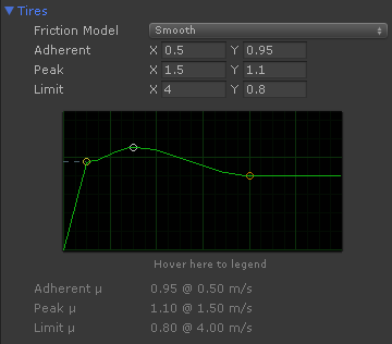
- For slips < 0.5 m/s the coefficient of friction is 0.95
- For slips > 0.5 m/s the coefficient of friction increases progressively up to 1.1 at 1.5 m/s.
- For slips > 1.5 m/s the coefficient of friction decreases progressively down to 0.8 at 4 m/s
- For slips > 4 m/s the coefficient remains constant at 0.8
The default tire setup is very forgiving and allows a good control of the vehicle in most situations.
A competition tire looks more like this:
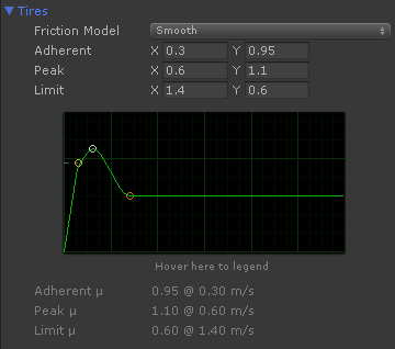
In this tire the peak friction (1.1) is reached at just 0.6 m/s. Any slip beyond that, and the friction rapidly drops 0.6. Real racing drivers have a great ability to apply the correct throttle to keep the tire at its maximum friction.
A more realistic friction shape can be achieved using the Pacejka friction model:
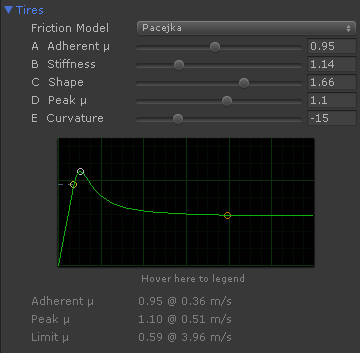
In this case Stiffness value to configures the slip where the curve reaches the peak friction at.
Understanding grip, torque and acceleration #
Torque is applied to the wheel. The tire converts the torque into a force at the contact point. This force is then applied to the rigidbody, causing acceleration and the actual motion of the vehicle.
The torque is generated by the engine and drivetrain connected to the drive wheels. While this torque can be nearly any magnitude, the grip actually limits the amount of force that is transmitted to the vehicle:
where
(N) is the maximum force the tire can transmit to the vehicle,
(N) is vertical downforce on the tire, and
is the coefficient of friction of the tire with the surface.
The force supported by the wheel depends on several factors: weight, acceleration, aerodynamics. When the vehicle is accelerating part of its weight is transfered from front to rear wheels. RWD (Rear Wheel Drive) vehicles have better acceleration because of the increased downforce on the drive wheels while accelerating provides extra grip. When the vehicle is braking part of the weight is transfered to the front wheels which get their grip increased while braking. This is why brake systems typically apply more brake power to the front wheels (brake bias).
Tip
The more weight the more grip but also less acceleration due to the vehicle's mass. As rule of thumb an acceleration of 1G requires all the wheels to perform a coefficient of friction of .
The coefficient of friction is given by the tire friction curve combined with the amount of slip. A simplified friction curve depends on the surface grip only. A realistic curve depends on many factors: camber, temperature, pressure, surface grip, vertical downforce, tire wear...
Aerodynamics have a huge influence on grip because it greatly increments at high speeds. Formula-1 vehicles can achieve a sustained lateral acceleration of 4G at high speed curves. Without the effect of aerodynamics this would mean tires with coefficient of friction of 4. Typical road tires can reach 1. Racing slick tires can perform in the range of 1.7 - 1.9. Only aerodynamics can increase the grip further.
When the torque is greater than the grip of the wheel, the excess of torque causes wheel spin, and the tire slips over the surface. In typical friction curves exceeding certain slip value reduces the grip. In addition, forward slip reduces the tire's sideways grip so the vehicle can easily slide sideways.
Tips for improving grip and acceleration
- Keep forward slip under control. A rev limiter can be set up in the engine so the first gear gets a controlled amount of spin, limiting the slip on standing starts.
- The Traction Control System (TCS) cuts the engine power for limiting the forward slip and thus increase the grip.
- Use aerodynamics for increasing grip at high speeds. Aerodynamic components must produce a balanced downforce among front and rear axles.
- Rear-Wheel-Drive and All-Wheel-Drive vehicles have better acceleration than Front-Wheel-Drive vehicles.
Steering, friction, lateral slip and lateral forces #
Here's a step-by-step explanation of the different factors involved on lateral tire forces and cornering rate:
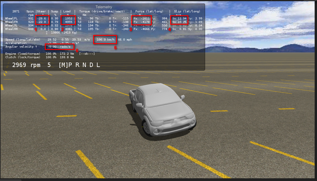
- Steering angle is 29 - 22 degrees for the front wheels (1)
- Speed is 106.3 km/h or 66 mph (5)
- Given the above steering angle and speed, the wheels are experiencing a lateral slip of 12 - 10 m/s (4)
- The slip applied to the tire friction curve results in a coefficient of friction of ~0.82 (not shown at the telemetry; more info below).
- Normal load on the wheels is 1952 - 4955 N (2)
- Given the above coefficient of friction and normal load, the wheels produce a lateral force of 1611 - 4178 N (3)
- The lateral forces applied to the vehicle produce an angular rotation rate of 0.30 rad/s or 17.2 deg/s (6). This means that at this speed the vehicle could complete a 90º turn in ~5.2 seconds.
This is the tire friction curve in the vehicle:
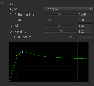
The peak friction is developed at 1.5 m/s. As the front wheels are experiencing 10-12 m/s, this means they are developing the minimum friction (a coefficient of friction of ~0.82).
Maximizing the lateral forces
- Use the Steering Limit aid for keeping the sideways slip close to the value where the maximum friction is developed. For example, a steering angle of 3 degrees in the scene above increases the cornering rate to 0.50 rad/s (= 28.6 deg/s, or just 3.15 seconds for completing a 90º turn).
- Adjust the tire friction curve so the maximum friction is developed at a value more closer to the typical sideways slip experienced by wheels. Combine this solution with the previous one.
- Configure the aerodynamic components to apply more downforce at the front wheels than at the rear wheels at high speeds. This may increase oversteer as well. rear wheels at high speeds. This may increase oversteer as well.
Converting an existing Pacejka set to VPP #
Standard Pacejka sets are based on slip ratio and slip angle while friction curves in VPP are based in slip velocity. Thus, standard Pacejka coefficients are not directly compatible with VPP. Still, existing Pacejka sets may be adapted to VPP following this procedure:
-
Define a velocity for the vehicle and a vertical load . Ideally, these should be the same values used for extracting the original Pacejka coefficients out of the real tire. If they are not available, use some representative velocity and load from the ranges the tire is designed to operate at.
-
Use some math software (Mathematica, Matlab) to draw the normalized tire friction curve:
is the force computed out of the Pacejka set being the vertical load, and the slip ratio () for the longitudinal Pacejka version, or the slip angle () for the lateral version:
where is horizontal value in the graph. So the longitudinal version would be:
And the lateral version:
-
Configure the tire friction in VPP to match the resulting curve as closely as possible. You may use either a Pacejka model or any of the other modes (i.e. Parametric), which are typically easier to fit to an existing curve.
Scripting Reference #
TireFriction #
namespace VehiclePhysics
{
[Serializable]
public class TireFriction
    {
    // Friction model and settings. Editable at the inspector.
    //
    // Any changes here by scripting must be followed by a call to SetupFrictionCurves()
    // for the changes to have effect.

    public Model model = Model.Smooth;
    public Settings settings = new Settings();

    // Generic friction multiplier. Tire force is multiplied by this factor.

    public float frictionMultiplier = 1.0f;

    // Speed below which the adherent friction is completely faded out.

    public float maxAdherentSpeed = 23.0f / 3.6f;

    // Supported friction models

    public enum Model
        {
        Flat,
        Linear,
        Smooth,
        Parametric,
        Pacejka
        }

    // Settings for defining any friction curve

    [Serializable]
    public class Settings
        {
        public float adherentFriction = 0.95f;                  // Linear, Smooth, Parametric
        public Vector2 peak = new Vector2(1.5f, 1.1f);          // Flat, Linear, Smooth, Parametric
        public Vector2 limit = new Vector2(6.0f, 0.8f);         // Linear, Smooth, Parametric

        // Parametric only: sharpness ratios (0 = smooth, 1 = sharp).

        [Range(0,1)] public float a = 0.9f;             // Sharpness of the ascending curve
        [Range(0,1)] public float b = 0.0f;             // Sharpness before the peak point
        [Range(0,1)] public float c = 0.0f;             // Sharpness after the peak point
        [Range(0,1)] public float d = 0.0f;             // Sharpness before the limit point

        // Pacejka (simplified version)

        [Range(0.01f,2)] public float A = 0.95f;        // Adherent coefficient of friction
        [Range(0.2f,4)] public float B = 0.8f;          // Stiffness
        [Range(1,2)]    public float C = 1.5f;          // Shape
        [Range(0,2)]    public float D = 1.1f;          // Peak coefficient of friction
        [Range(-20,1)]  public float E = -2.0f;         // Curvature
        }
    }

    // Properties of the actual contact patch of the tire with the surface

    public class ContactPatch
        {
        public float load = 1.0f;
        public Vector2 slip = Vector2.zero;
        public Vector2 localVelocity = Vector2.zero;
        public float groundGrip = 1.0f;
        }

    // Configure the friction curve out of the actual settings

    public void SetupFrictionCurves ()

    // Isotropic friction implementation (single friction curve)

    public Vector2 GetForce (ContactPatch cp)

    // Returns whether current slip falls inside the adherent cone

    public bool IsAdherentSlip (ContactPatch cp)
    float GetAdherentSlip (ContactPatch cp)

    // Compute the maximum forward adherent force (return value) as well as the maximum
    // forward adherent slip (cp.slip.y) for the current sideways slip.
    //
    // Fordward force is signed.

    public float ComputeAdherentForceForward (ContactPatch cp)

    // Compute the maximum sideways adherent force (return value) as well as the maximum
    // sideways adherent slip (cp.slip.x) for the current forward slip.
    //
    // Sideways force is unsigned (friction force)

    public float ComputeAdherentForceSideways (ContactPatch cp)

    // Return the slip bounds of the adherent circle (isotropic)

    public Vector2 GetAdherentSlipBounds (ContactPatch cp)

    // Return the slip bounds of the peak circle (isotropic)

    public Vector2 GetPeakSlipBounds (ContactPatch cp)

    // Return the slip bounds of the limit circle (isotropic)

    public Vector2 GetLimitSlipBounds (ContactPatch cp)
    }
}