Engine block #
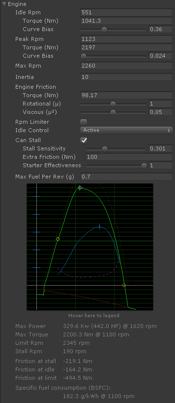
The Engine block simulates a standard combustion engine. It provides output torque in Nm based on the configuration (green curve in the graph). As result of the torque and the rpm range the engine develops the corresponding power in kW or HP (blue curve in the graph).
The simulation includes torque curve, inertia, engine friction curve, rpm limiter, idle control with throttle mapping, stall, engine ignition and fuel consumption.
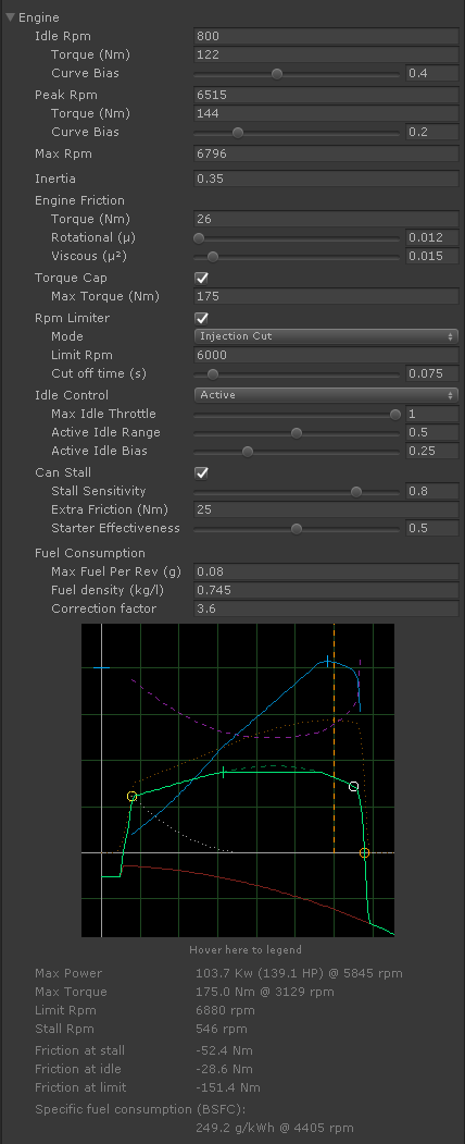
Engine Graph #
Horizontal: rpm. Vertical: torque in Nm, power in Kw.
- Solid green: engine torque (Nm). Vertical mark at the peak torque.
- Solid blue: engine power (Kw). Vertical mark at the peak power.
- Solid red: engine friction torque (Nm).
- Circles: configured torque and rpm values (Idle Rpm, Peak Rpm and Max Rpm parameters).
- Dashed green: engine torque without torque cap (Nm) (Torque Cap option).
- Dotted orange: raw combustion torque (Nm). Engine torque results of subtracting the engine friction torque from this combustion torque.
- Dashed purple: specific fuel consumption (g/kWh) (Fuel Consumption parameters).
- Dotted white: throttle map at idle and low rpm (Active Idle parameters).
- Vertical dashed orange: configured rpm limit (Rpm Limiter option).
Engine Specifications #
- Max Power: maximum engine power in Kw and Hp and its rpm.
- Max Torque: maximum engine torque in Nm and its rpm. If Torque Cap is enabled the rpm is the first point where the torque cap is enforced.
- Limit Rpm: beyond this rpm the engine is not producing any more torque, only friction torque.
- Stall Rpm: the engine stalls if rpm fall below this value.
- Friction at stall: engine friction when the engine is stalled
- Friction at idle: engine friction at Idle Rpm. The engine must apply some torque (hence consume some fuel) when idle to counteract this friction.
- Friction at limit: engine friction at Limit Rpm. The engine cannot counteract any part of this friction.
- Specific Fuel Consumption (BSFC): The calculated value for Brake Specific Fuel Consumption (BSFC). Sometimes the specifications of real engines provide this value.
Torque Curve #
The torque curve is mostly defined with the Idle, Peak and Max Rpm parameters. Circles in the graph represent these settings (horizontal: rpm, vertical: torque in Nm). Curve Bias adjusts the shape of the curve.
The actual engine specifications (Max Power, Max Torque, etc) are calculated and displayed below the graph.
- Idle Rpm
- Rpm, torque (Nm) and curve bias when no throttle is applied.
- Peak Rpm
- Rpm, torque (Nm) and curve bias when the engine generates most raw combustion torque. Due to the engine friction the actual peak torque may be produced at different rpm (check specifications below the graph).
- Max rpm
- Maximum rpm the engine can reach with its own torque.
Inertia #
The rotational inertia of the engine as measured in the output shaft (kg·m²).
This value defines how the engine resist to changes in its rpm. Higher values reduce the rpm change rate. Lower values increase the rpm change rate. In other words, higher inertia values require more torque to change the rpm, and lower values require less torque to change rpm.
Main effects of the engine inertia:
- How fast the rpm change when pressing and releasing throttle.
- Engine brake, especially when braking and upshifting.
Engine friction #
Torque exerted by the engine when throttle is not applied as measured in the output shaft (Nm). Engine friction configures:
- The engine brake based on rpm.
- How fast the engine returns to idle rpm when lifting throttle in neutral.
Engine friction torque is calculated as:
Where is the resulting engine friction torque in Nm and is the angular velocity of the engine in rad/s.
- Torque
- frictionTorque in the formula. Minimum friction torque (Nm) always applied by the engine.
- Rotational
- rotationalFriction in the formula. Coefficient multiplied by the angular velocity.
- Viscous
- viscousFriction in the formula. Coefficient multiplied by the angular velocity squared.
Torque Cap #
Torque Cap configures an upper limit to the engine torque (Nm). Many engines have an electronic limitation in their torque across a range of rpm.
- Max Torque
- Maximum torque (Nm) the engine can provide. The "unused" torque above the limit is shown in the graph as dashed green.
Torque cap also reduces the fuel consumption in the rpm range where the limit is applied.
Rpm Limiter #
Rpm limiter configures an upper limit to the rpm the engine can reach by actively producing torque. When enabled, the rpm limit is shown in the graph as vertical dashed orange.
- Mode
-
Action to take when the engine reaches the Limit Rpm.
- Injection Cut: stops applying torque for an amount of time (Cut Off Time), allowing the rpm to fall below the limit.
- Injection Limit: smoothly reduces the engine torque so the rpm stays steadily at the limit.
- Limit Rpm
- Maximum rpm value allowed.
- Cut Off Time
- In Injection Cut mode, this is the time (s) the torque is stopped when reaching the Limit Rpm value
Idle Control #
Defines how to apply the torque that keeps the engine at idle rpm and prevent it to stall.
- Passive: The engine applies the exact torque that compensates the friction torque at idle rpm. Works better with a steep friction curve.
- Active: Vehicle's electronic system actively applies as much torque as available for keeping the idle rpm.
- Max Idle Torque
- Percent of the total engine torque that can be used to prevent the rpm to fall below Idle Rpm.
Active Idle #
Active Idle maps the throttle torque with respect to the torque at Idle Rpm. This avoids null or inactive zones in the throttle pedal range at Idle Rpm. These parameters also define the response of the throttle pedal at low rpm values. The Active Idle mapping curve is shown in the graph as dotted white.
- Active Idle Range
- Percent of the rpm range where the throttle torque is mapped with respect to the torque at Idle Rpm.
- Active Idle Bias
- Shape of the throttle mapping curve with respect to the torque at Idle Rpm.
Can Stall #
Can Stall allows the engine to stall. When the engine is stalled the ignition key may be used to start the engine. The engine may also be started "inertially", that is, leave the car roll on a slope to gain some velocity, press clutch, engage a gear and release clutch.
- Stall Sensitivity
- How easy is to stall the engine once the rpm fall below Idle Rpm. The more value, the easier to stall.
- Extra Friction
- When the engine is stalled it applies this extra amount of friction torque (Nm).
- Starter Effectiveness
-
How effective is the starter motor when starting a stalled engine. This is a somewhat "subjective" value that behaves differently in each engine setup. The more value, the faster and more reliably the engine starts. The lower value, the harder to start. Below some point the engine won't start at all.
This may be used to simulate a drained battery or difficult weather conditions (i.e. start the engine in low temperatures).
Fuel Consumption #
The parameters for fuel consumption define the Instant Fuel Consumption rate in grams per second (g/s) that can be read in the Data Bus (Vehicle channel, EngineFuelRate entry).
- Max Fuel Per Rev
- Maximum amount of fuel in grams (g) the engine can "swallow" in a single rev when applying full throttle. This parameter defines the specific fuel consumption (BSFC) of the engine.
- Fuel Density
-
Fuel density (kg/l) for the instant fuel consumption calculation.
- Petrol (gasoline): 0.745 kg/l
- Diesel: 0.85 kg/l
- Correction Factor
-
Efficiency correction factor that accounts for all factors that affect the fuel consumption value as l/100km. Adjust for matching the fuel consumption rates observed in the real vehicle or engine. Higher values report lower consumption rates.
- 3.6 seems to work fine for regular cars
- Trucks seem to use 1.8 - 3.5
References:
Brake Specific Fuel Consumption (BSFC)
Fuel consumption analysis of motor vehicle
Fuel densities
Understanding Engine Curves #
The engine torque curve (green) is the sum of the raw combustion torque (dotted yellow) and the engine friction (red).
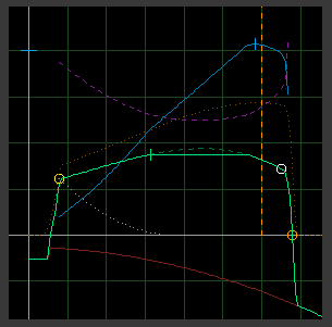
Dyno curves show only the final torque and power curves. They won't show the engine friction. The shape of the torque curve and is relationship with the power curve gives us clues on how the engine friction should be configured. Engine braking is a commonly ignored specification, yet a critical parameter that the shape of the torque curve and the engine behavior.
The Engine parameters in Vehicle Physics Pro the define specific points (circles in the graph) that will be crossed by the final engine torque curve (green). But it doesn't mean these points will make a maximum or minimum torque, for example. The rpm range in the real dyno charts is typically cropped. Real tests won't likely push the engine until the torque actually results zero, as the rev limiter will be cutting down the injection first. So you must figure out which torque curve would result if the engine would be pushed beyond the rev limiter. Max Rpm is the rpm where the raw torque has decreased so much that is entirely canceled by the engine friction and the final torque results zero. Only friction torque can be produced beyond Max Rpms. This settings is deduced based on the shape of the real dyno chart.
The peak point (white circle in the graph) represent the point where the raw combustion provides the maximum torque. This raw friction (dotted orange) always increases before the peak rpm, and decreases after it. Once the engine friction is subtracted from the raw torque you get the actual engine torque. The point of maximum engine torque the small vertical white line crossing the green torque curve.
The difficulty on setting up the engine curves is that you need to figure out both the raw torque and the friction torque so they result in the final torque curve that fits the real specifications. It's not trivial and requires a bit of practice. But most engines can be configured with good precision.
Example 1: peak torque #
This is the curve and specifications from the figure at the top:
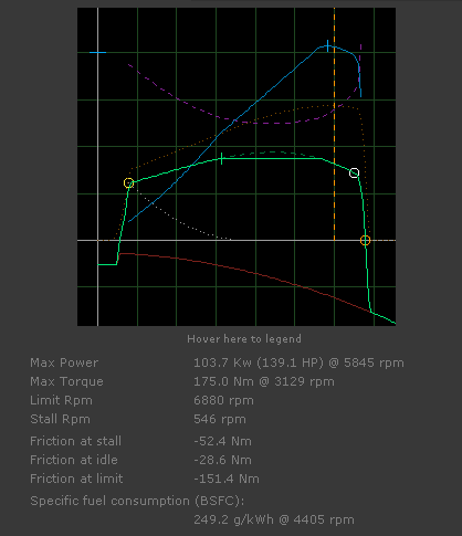
Note how the maximum torque is reached at 3129 rpm while the "Peak Rpm" setting is 6515. This Peak Rpm is the point of maximum raw combustion torque (dotted yellow). Additionally, the rev limiter won't let the engine go beyond 6000 rpms. The original specifications are cropped just at that point.
Example 2: engine curve vs. real specs #
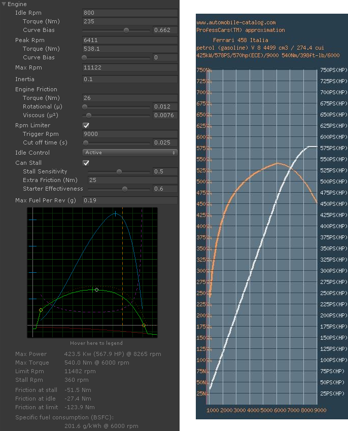
This is a very good curve fit. Max Torque matches the specifications exactly (540 Nm @ 6000 rpms), and the Max Power is very close as well (423.5 vs. 425 kW). The flat end in the power curve surely represents an electronically imposed power correction, as it doesn't fit with the other curve data.
Example 3: truck engine #
A radically different example is a truck engine. These engines provide a lot of torque at very low rpm. These parameters closely match the specifications of the real model:
Scripting Reference #
namespace VehiclePhysics
{
    public class Engine : Block
}
Properties #
    public enum IdleControlType { Passive, Active };
    public enum ClutchType { LockRatio, FrictionDisc, TorqueConverter, TorqueConverterLimited };
    public enum RpmLimiterMode { InjectionCut, InjectionLimit };

    public float throttleInput = 0.0f;          // 0.0 = no throtle, 1.0 = full throttle
    public float clutchInput = 0.0f;            // 0.0 = disengaged, 1.0 = engaged
    public int ignitionInput = 0;               // -1 = off, 0 = acc-on, 1 = start

    public float allowedFuelRatio = 1.0f;       // 0.0 = no fuel consumption allowed. 1.0 = regular operation

    public float tcsRpms = -1.0f;               // Hinted RPMs come from TCS and similar systems.
    public float tcsRatio = 1.0f;               // "Effectiveness" of the hinted RPMs.
    public float tcsThrottleFactor = 1.0f;      // TCS-computed throttle will be limited by this factor.

    public bool autoRpms = false;               // AutoRpms overrides all other throttle considerations
    public float targetRpms = -1.0f;            // (rpm limiter, throttleInput, TCS, ...)

    public Settings settings = new Settings();
    public ClutchSettings clutchSettings = new ClutchSettings();

    public static float KwToHp = 1.341022f;     // Mechanical Horsepower
                                                // https://www.rapidtables.com/convert/power/kw-to-hp.html
    // Sensors exposing internal data

    public float sensorRpm              { get; }
    public bool sensorStalled           { get; }
    public bool sensorWorking           { get; }
    public bool sensorStarting          { get; }
    public float sensorFlywheelTorque   { get; }
    public float sensorOutputTorque     { get; }
    public float sensorPower            { get; }
    public bool sensorRpmLimiter        { get; }
    public bool sensorTcsEngaged        { get; }
    public float sensorFuelRate         { get; }

    // Load and clutch lock return NaN when the info is not available.

    public float sensorLoad             { get; }
    public float sensorClutchLock       { get; }

    // Numerical damping heps preventing resonances, but also reduces the precision of the values.

    public float damping = 1.0f;
Nested classes #
    // Engine settings

    [Serializable]
    public class Settings
        {
        public float idleRpm = 1000.0f;
        public float peakRpm = 4200.0f;
        public float maxRpm = 6500.0f;

        public float idleRpmTorque = 135.0f;
        public float peakRpmTorque = 188.0f;

        [Range(0,1)]
        public float idleRpmCurveBias = 0.0f;
        [Range(0,1)]
        public float peakRpmCurveBias = 0.0f;

        public float inertia = 0.5f;

        public float frictionTorque = 20.0f;        // Passive friction torque in Nm, constant
        [Range(0,3.0f)]
        public float rotationalFriction = 0.1f;     // Rotational friction coefficient, lineal, based on w
        [Range(0,0.2f)]
        public float viscousFriction = 0.01f;       // Viscous friction coefficient, cuadratic, based on w^2

        public bool torqueCap = false;
        public float torqueCapLimit = 200.0f;

        // Rev limiter

        public bool rpmLimiter = false;
        public RpmLimiterMode rpmLimiterMode = RpmLimiterMode.InjectionCut;
        public float rpmLimiterMax = 6000.0f;
        [Range(0,1)]
        public float rpmLimiterCutoffTime = 0.075f;

        // Idle

        public IdleControlType idleControl = IdleControlType.Active;
        [Range(0,1)]
        public float maxIdleThrottle = 1.0f;
        [Range(0,1)]
        public float activeIdleRange = 0.5f;
        [Range(0.0001f,0.9999f)]
        public float activeIdleBias = 0.25f;

        // Stall

        public bool canStall = false;
        [Range(0,1)]
        public float stallBias = 0.5f;
        public float stalledFrictionTorque = 25.0f; // Torque (Nm) added to the friction when engine is stalled
        [Range(0,1)]
        public float starterMotorBias = 0.6f;       // "Reliability" factor of the starter motor

        // Fuel consumption
        // Maximum fuel consumed by the engine in a single rev at full load (grams / rev).
        // This parameter defines the specific fuel consumption (BSFC) of the engine.

        public float maxFuelPerRev = 0.16f;

        // Fuel density for the consumption calculation (l/100km) in Kg/l
        // - Petrol (gasoline): 0.745f
        // - Diesel: 0.85f

        public float fuelDensity = 0.745f;

        // Efficiency correction factor that account for all factors that affect the fuel consumption value as l/100km.
        // Adjust for matching the fuel consumption rates observed in real vehicles.
        //
        // - 3.6 seems to work fine for regular cars
        // - Trucks seem to use 1.8 - 3.5
        //
        // (higher values report lower consumption rates)

        public float fuelConsumptionCorrection = 3.6f;
        }

    // Read-only specifications of the engine based on the settings

    public struct EngineSpecs
        {
        public float idleRpm;                   // Rpm at idle
        public float maxTorqueAtIdle;           // Max torque provided at idle rpm
        public float frictionTorqueAtIdle;      // Engine friction at idle rpm when no throttle is applied

        public float peakRpm;                   // Rpm with max torque
        public float maxTorqueAtPeak;           // Maximum torque of the engine. It's provided at peakRpm.
        public float frictionTorqueAtPeak;      // Engine friction at peak rpm when no throttle is applied
        public float specificFuelConsumption;   // Specific fuel consumption (fuel / kWh)
        public float specificFuelConsumptionRpm;// Rpms

        public float maxPowerRpm;               // Rpm with max power
        public float maxPowerInKw;              // Max engine power in Kw. It's developed at maxPowerRpm.
        public float maxPowerInHp;              // The previous value converted to HP.

        public float limitRpm;                  // Beyond this limit combustion cannot produce any further torque even at full throttle
        public float frictionTorqueAtLimit;     // Engine friction at the operational limit
        public float stallRpm;                  // Below this limit engine is unable to keep a minimum torque and stalls
        public float frictionTorqueAtStall;     // Engine friction that must be surpassed for the engine to start

        // Information flags for malformed engine curves

        public bool malformedTorque;            // Torque (green) cannot be negative before maxRpm
        public bool malformedRawPower;          // Raw engine power (dotted orange) must be decreasing after peakRpm
        }
Methods #
    // Retrieve engine specifications for the current settings

    public void GetEngineSpecifications (ref EngineSpecs data, float deltaRpm = -1.0f)

    // Calculate maximum torque
    //
    // Given the input rpms calculate and return the actual torque produced by the engine.
    //
    // Used for informative purposes only (specifications, graphics). The real curve is
    // calculated in EvaluateTorqueDownstream.

    public float CalculateTorque (float rpm, float throttle = 1.0f)

    // Calculate engine power
    //
    // Used for drawing the power curve and find the maximum engine power.
    // It has no other practical utility.

    public float CalculatePowerInKw (float rpm)

    // Calculate specific fuel consumption (g/kWh)
    //
    // Detailed calculation based on https://en.wikipedia.org/wiki/Brake_specific_fuel_consumption
    //
    // float fuelConsumptionRate = m_engine.GetMaxFuelRate(y);
    // float torque = m_engine.CalculateTorque(y);
    // float w = y * Block.RpmToW;
    // float bsfc = fuelConsumptionRate / (w * torque);  // grams per joule (g/J)
    // return bsfc * 3.6f * 1000000f;

    public float CalculateSpecificFuelConsumption (float rpm)

    // Calculate the instant fuel consumption in l/100km at the current fuel rate for the given speed.

    public float CalculateInstantFuelConsumption (float speed)

    // Apply friction torque externally by calling AddFrictionTorque on each fixed frame step

    public float AddFrictionTorque (float frictionTorque)
    public void ResetFrictionTorque ()

    // Get / set the state vars
    //
    // Used for getting the state of the engine and restoring it exactly.

    public StateVars GetStateVars ()
    public void SetStateVars (StateVars stateVars)
Populating the Data bus #
A custom vehicle controller using the Engine block should populate the vehicle's data bus so all other components attached to the vehicle can read the engine and clutch state from the bus.
Add this code to the overridden VehicleBase.DoUpdateData() method in your controller to populate
the data bus correctly. m_engine is the private var with the Engine block instance.
protected override void DoUpdateData ()
    {
    // Access to the vehicle info channel
    int[] vehicleData = data.Get(Channel.Vehicle);

    // speed is inherited from VehicleBase
    vehicleData[VehicleData.Speed] = (int)(speed * 1000.0f);

    // Engine state
    vehicleData[VehicleData.EngineRpm] = (int)(m_engine.sensorRpm * 1000.0f);
    vehicleData[VehicleData.EngineStalled] = m_engine.sensorStalled? 1 : 0;
    vehicleData[VehicleData.EngineWorking] = m_engine.sensorWorking? 1 : 0;
    vehicleData[VehicleData.EngineStarting] = m_engine.sensorStarting? 1 : 0;
    vehicleData[VehicleData.EngineLimiter] = m_engine.sensorRpmLimiter? 1 : 0;
    vehicleData[VehicleData.EngineTorque] = (int)(m_engine.sensorFlywheelTorque * 1000.0f);
    vehicleData[VehicleData.EnginePower] = (int)(m_engine.sensorPower * 1000.0f);
    vehicleData[VehicleData.EngineLoad] = m_engine.sensorLoad < 0.0f? -1 : (int)(m_engine.sensorLoad * 1000.0f);
    vehicleData[VehicleData.EngineFuelRate] = (int)(m_engine.sensorFuelRate * 1000.0f);
    vehicleData[VehicleData.FuelConsumption] = (int)(m_engine.CalculateInstantFuelConsumption(speed) * 1000.0f);

    // Clutch state
    vehicleData[VehicleData.ClutchTorque] = (int)(m_engine.sensorOutputTorque * 1000.0f);
    vehicleData[VehicleData.ClutchLock] = (int)(m_engine.sensorClutchLock * 1000.0f);

    // TCS state
    vehicleData[VehicleData.TcsEngaged] = m_engine.sensorTcsEngaged? 1 : 0;

    // Actual inputs applied to engine and clutch
    vehicleData[VehicleData.ThrottleSignal] = (int)(m_engine.throttleInput * 10000.0f);
    vehicleData[VehicleData.ClutchSignal] = (int)(m_engine.clutchInput * 10000.0f);
    }